
Description
This three-phase oil-immersed distribution transformer is with a new insulation structure to improve short-circuit resistance.
The iron core is made of high-quality cold-rolled silicon steel sheets. The high-voltage winding is made of high-quality oxygen-free copper wire and adopts a multi-layer cylindrical structure. All fasteners are treated with special anti-loosening treatment.
The three-phase oil-immersed distribution transformer has the characteristics of high efficiency and low loss, which can save a lot of electricity consumption and operating costs, and has significant social benefits. It is a high-tech product promoted by country.
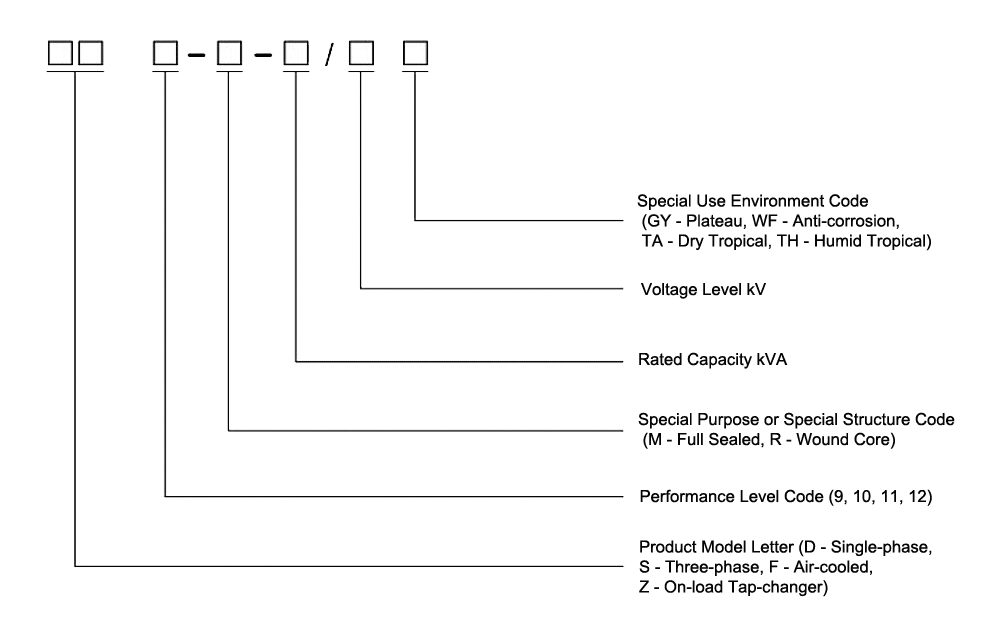
Model Designation
Reliable Structure
Based on the traditional structure and mature technology, our company has made many improvements, such as:
◆ Adoption of spiral coils with longitudinal oil channels for improved internal heat dissipation;
◆ Improved effective support on the coil end face for better resistance to short-circuit current;
◆ Adoption of a new lifting structure and body positioning structure to ensure greater reliability during long-distance transportation and operation;
◆ we also have many unique and reliable structures at your service;
The selection of transformers with higher performance level will have a higher level of technology.
Technical Parameters
| Rated Capacity(KVA) | Voltage Group(KV) | Vector Group | No-load Loss(W) | Load Loss (KW) | No-Load Current(%) | Impedance Voltage(%) | Weight (kg) | Dimensions(mm) (L×B×H) | Mounting Dimensions(mm) |
| 10 | 11 10 6 / 0.4 | Dyn11 / Yyn0 | 60 | 400 | 2.5 | 4 | 170 | 560×370×850 | 400/400 |
| 20 | 80 | 520 | 1.9 | 220 | 620×500×870 | 400/400 | |||
| 30 | 100 | 630/600 | 1.5 | 280 | 680×520×880 | 400/400 | |||
| 50 | 130 | 910/870 | 1.3 | 310 | 680×550×910 | 400/400 | |||
| 63 | 150 | 1090/1040 | 1.2 | 360 | 710×560×920 | 400/400 | |||
| 80 | 180 | 1310/1250 | 1.2 | 390 | 730×580×950 | 400/400 | |||
| 100 | 200 | 1580/1500 | 1.1 | 470 | 760×670×1000 | 400/400 | |||
| 125 | 240 | 1890/1800 | 1.1 | 510 | 1000×690×1000 | 400/400 | |||
| 160 | 280 | 2310/2200 | 1 | 630 | 1010×700×1080 | 550/550 | |||
| 200 | 340 | 2730/2600 | 1 | 680 | 1110×790×1100 | 550/550 | |||
| 250 | 400 | 3200/3050 | 0.9 | 790 | 1180×800×1110 | 550/550 | |||
| 315 | 480 | 3830/3650 | 0.9 | 900 | 1230×910×1140 | 550/550 | |||
| 400 | 570 | 4520/4300 | 0.8 | 1070 | 1340×950×1220 | 660/660 | |||
| 500 | 680 | 5410/5150 | 0.8 | 1270 | 1440×1030×1250 | 660/660 | |||
| 630 | 810 | 6200 | 0.6 | 4.5 | 1580 | 1600×1160×1310 | 660/660 | ||
| 800 | 980 | 7500 | 0.6 | 1830 | 1680×1220×1350 | 660/660 | |||
| 1000 | 1150 | 10300 | 0.6 | 2150 | 1700×1220×1440 | 820/820 | |||
| 1250 | 1360 | 12000 | 0.5 | 2800 | 1760×1280×1540 | 820/820 | |||
| 1600 | 1640 | 14500 | 0.5 | 3100 | 1780×1290×1640 | 820/820 | |||
| 2000 | 1940 | 18300 | 0.4 | 5 | 3800 | 1850×1310×1650 | 820/820 | ||
| 2500 | 2290 | 21200 | 0.4 | 4650 | 1910×1880×1750 | 820/820 | |||
| Note: 1. Transformers with other voltages can be provided according to user requirements. 2. The losses above the slash are for Dyn11 or Yzn11. 3. High-voltage tapping range is ±5% or ±2×2.5%; 50/60Hz | |||||||||