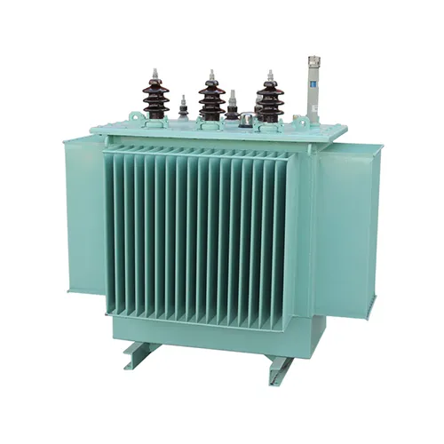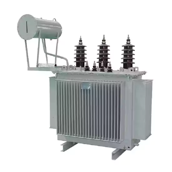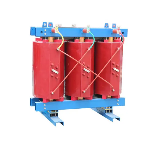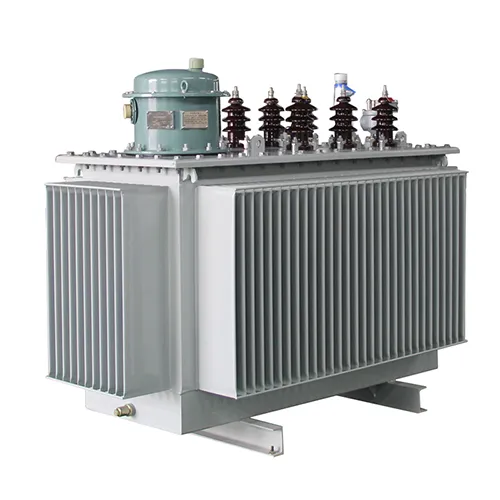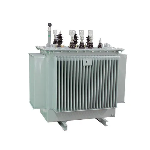
The S13 transformer is a new - generation, high - efficiency and energy - saving oil - immersed distribution transformer. It adopts advanced design concepts and manufacturing processes. It stands out for its remarkable energy - saving effects. Compared with the S11 transformer, its no - load loss is reduced by approximately 25%, and the load loss also decreases to a certain degree. The S13 transformer also has a strong short - circuit resistance ability. By improving the mechanical structure and materials of the windings, the mechanical strength of the windings is enhanced. This enables it to effectively withstand the impact of electrodynamic forces when facing short - circuit faults, ensuring the safe and stable operation of the transformer.
This three-phase oil-immersed distribution transformer is with a new insulation structure to improve short-circuit resistance.
The iron core is made of high-quality cold-rolled silicon steel sheets. The high-voltage winding is made of high-quality oxygen-free copper wire and adopts a multi-layer cylindrical structure. All fasteners are treated with special anti-loosening treatment.
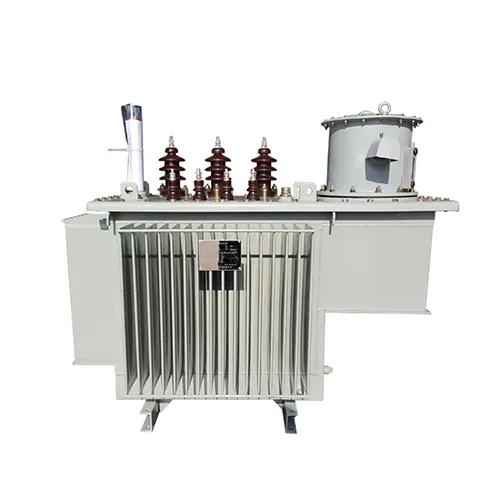
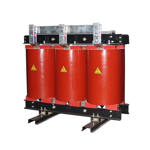
The three-phase oil-immersed distribution transformer has the characteristics of high efficiency and low loss, which can save a lot of electricity consumption and operating costs, and has significant social benefits. It is a high-tech product promoted by country.
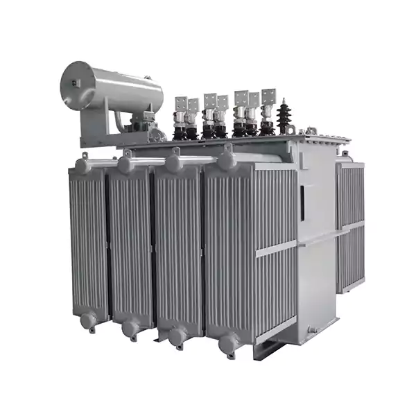
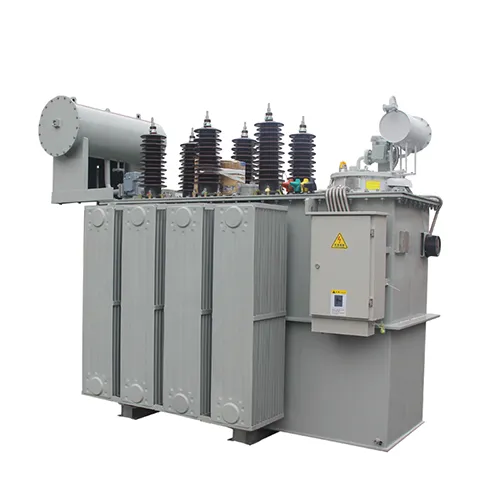
Based on the traditional structure and mature technology, our company has made many improvements, such as:
◆ Adoption of spiral coils with longitudinal oil channels for improved internal heat dissipation.
◆ Improved effective support on the coil end face for better resistance to short-circuit current.
◆ Adoption of a new lifting structure and body positioning structure to ensure greater reliability during long-distance transportation and operation.
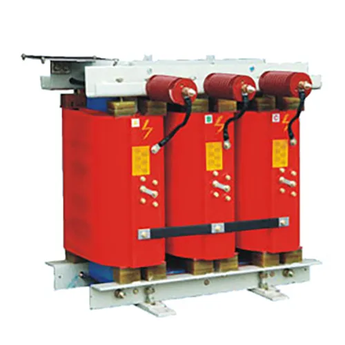
◆ we also have many unique and reliable structures at your service.
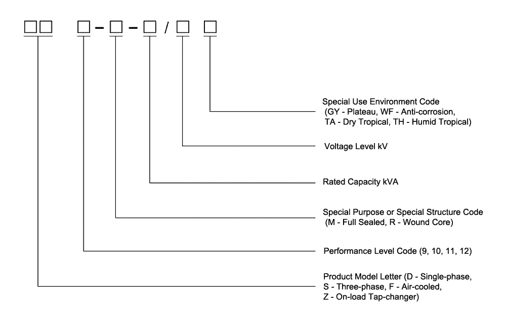
The selection of transformers with higher performance level will have a higher level of technology.
| Rated Capacity(KVA) | Voltage Group(KV) | Vector Group | No-load Loss(W) | Load Loss (KW) | No-Load Current(%) | Impedance Voltage(%) | Weight (kg) | Dimensions(mm) (L×B×H) | Mounting Dimensions(mm) |
| 10 | 11 10 6 / 0.4 | Dyn11 / Yyn0 | 40 | 400 | 2.5 | 4 | 170 | 560×370×850 | 400/400 |
| 20 | 40 | 520 | 1.9 | 220 | 620×500×870 | 400/400 | |||
| 30 | 80 | 630/600 | 1.5 | 280 | 680×520×880 | 400/400 | |||
| 50 | 100 | 910/870 | 1.3 | 310 | 680×550×910 | 400/400 | |||
| 63 | 110 | 1090/1040 | 1.2 | 360 | 710×560×920 | 400/400 | |||
| 80 | 130 | 1310/1250 | 1.2 | 390 | 730×580×950 | 400/400 | |||
| 100 | 150 | 1580/1500 | 1.1 | 470 | 760×670×1000 | 400/400 | |||
| 125 | 170 | 1890/1800 | 1.1 | 510 | 1000×690×1000 | 400/400 | |||
| 160 | 200 | 2310/2200 | 1 | 630 | 1010×700×1080 | 550/550 | |||
| 200 | 240 | 2730/2600 | 1 | 680 | 1110×790×1100 | 550/550 | |||
| 250 | 290 | 3200/3050 | 0.9 | 790 | 1180×800×1110 | 550/550 | |||
| 315 | 340 | 3830/3650 | 0.9 | 900 | 1230×910×1140 | 550/550 | |||
| 400 | 410 | 4520/4300 | 0.8 | 1070 | 1340×950×1220 | 660/660 | |||
| 500 | 480 | 5410/5150 | 0.8 | 1270 | 1440×1030×1250 | 660/660 | |||
| 630 | 570 | 6200 | 0.6 | 4.5 | 1580 | 1600×1160×1310 | 660/660 | ||
| 800 | 700 | 7500 | 0.6 | 1830 | 1680×1220×1350 | 660/660 | |||
| 1000 | 830 | 10300 | 0.6 | 2150 | 1700×1220×1440 | 820/820 | |||
| 1250 | 970 | 12000 | 0.5 | 2800 | 1760×1280×1540 | 820/820 | |||
| 1600 | 1170 | 14500 | 0.5 | 3100 | 1780×1290×1640 | 820/820 | |||
| 2000 | 1380 | 18300 | 0.4 | 5 | 3800 | 1850×1310×1650 | 820/820 | ||
| 2500 | 1640 | 21200 | 0.4 | 4650 | 1910×1880×1750 | 820/820 | |||
| Note: 1. Transformers with other voltages can be provided according to user requirements. 2. The losses above the slash are for Dyn11 or Yzn11. 3. High-voltage tapping range is ±5% or ±2×2.5%; 50/60Hz | |||||||||
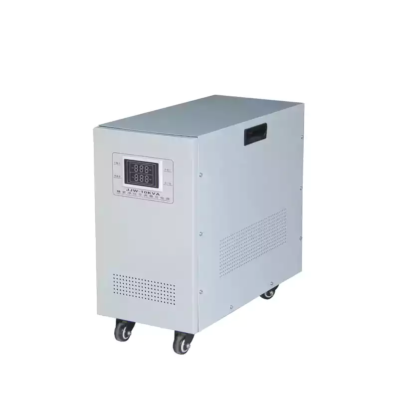
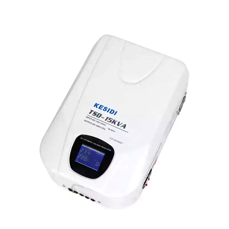
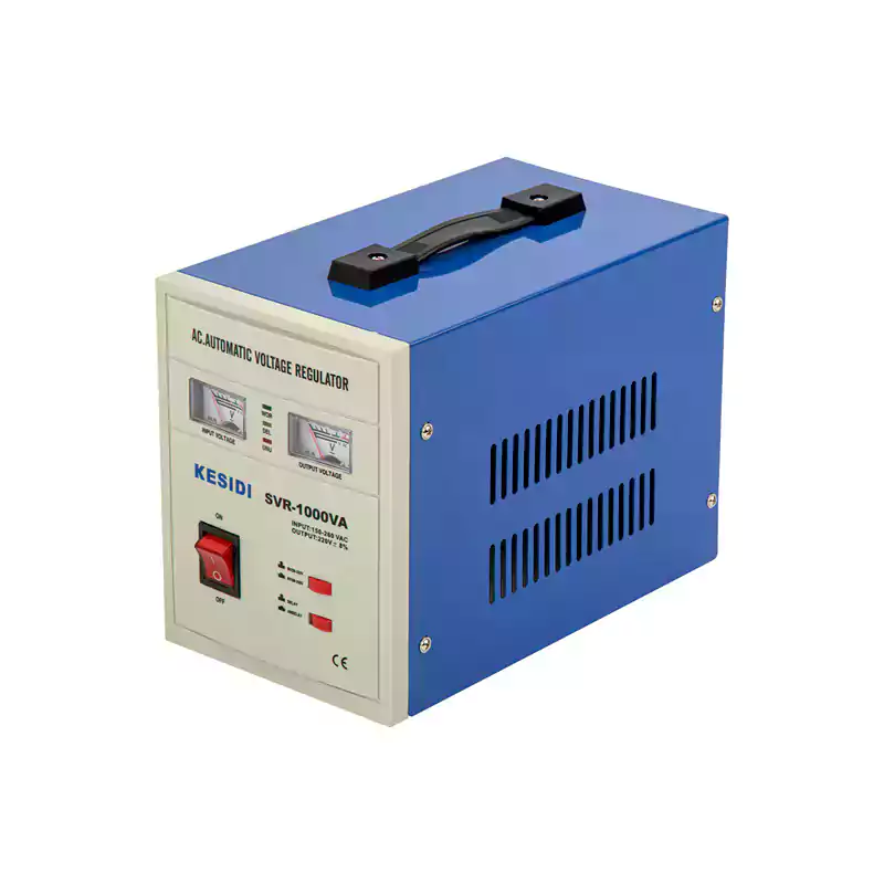
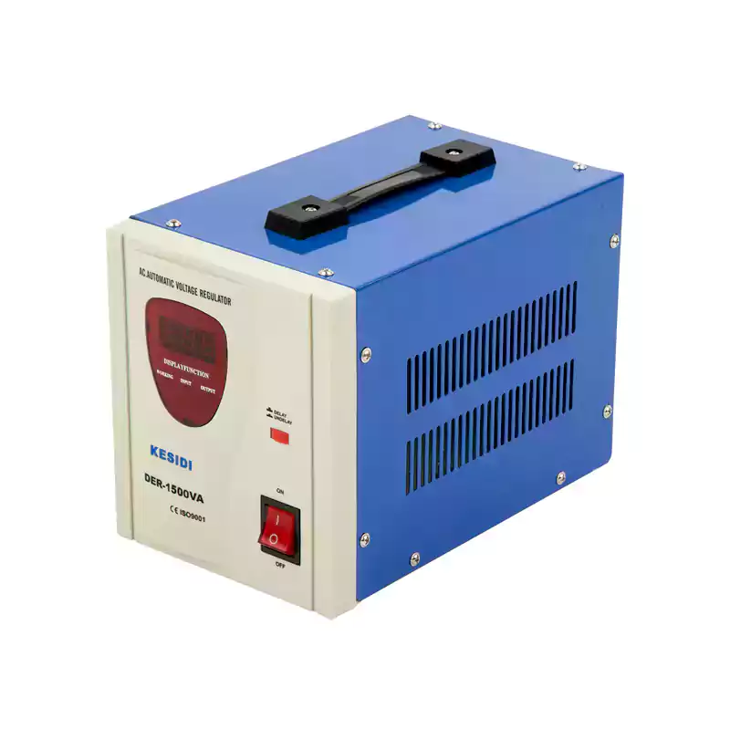
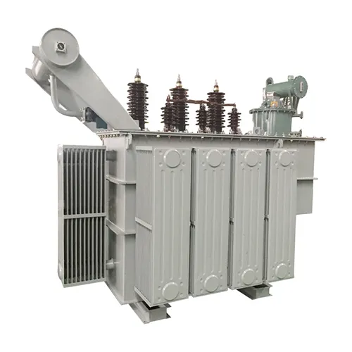
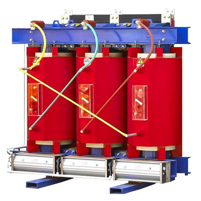
 Related Products